|
| How Plane Irons Wear |
|
| Finest abrasives. | ||
| Microbevels front and back. | ||
| Use a jig. | ||
| Copyright (c) 2002-15, Brent Beach |
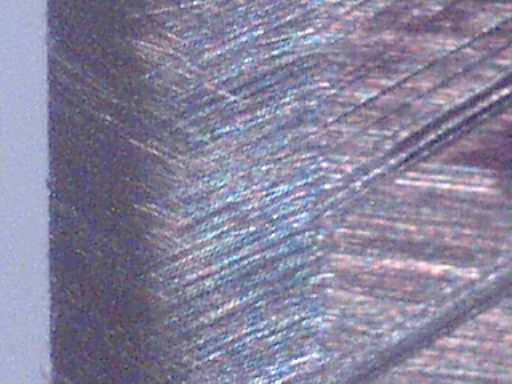
Just to illustrate the various parts of the worn blade, below is an image of the front bevel of a Clifton blade after 200 passes on a 4 foot Douglas-fir board. I have done a large number of plane iron tests on boards take from the same part of a large Douglas-fir tree that blew down 4 years ago on our property. The wear shown on this blade is an accurate comparison of the durability of this blade with other blades I have tested.
The picture was taken with a QX3 microscope at the 200X setting. This image corresponds to 0.03" of the blade at the edge, and represents a length of about 0.025" along the edge.
Clifton ships this blade with a 25 degree bevel (region 1). I added two microbevels during preparation of the blade (regions 3 and 2). Using the blade added the wear bevel (region 4). This first image is of a sharpened blade after 200 passes along a 4' Douglas-fir board. I wanted to show the wear bevel right away, in context of the honing bevels.
Worn Blade
|
The 4 regions are:
|

|
 The following picture shows 5 images of the edge of the same blade as in the above picture - after 0, 50, 100, 150, and 200 passes of the test. In all cases the edge is on the right side of the picture. I have aligned the edges so help with the comparison of wear after each series of passes.
|
|
I thought about leaving the back of this blade flat for this test [more closely simulating how most people prepare their irons], or even using conventional techniques to flatten the back.
A close look at the back of the blade - a blade which Clifton advertises as being usable without honing - convinced me to use my standard back bevel honing procedure. I believe that Clifton uses a high-speed grinding technique to prepare these irons. I don't believe you can properly prepare a plane iron with any high speed grinding process. People who flatten the back of the iron have a considerable challenge ahead of them. I have moved a small rant on this type of deceptive advertising out of the stream of the text. |

|
Here is the back of the blade after sharpening and before use. Again, there are 3 regions corresponding to three bevel angles.
|

|
 This composite of 5 pictures shows the back wear bevel as it changed during the test.
|
 High Wear Bevel
This very narrow back "high wear bevel" shows up as the darker area right at the edge in this digital enlargement of the last image above - after 200 passes. The high wear bevel is the slightly darker region at the edge. It is about 0.0002" wide. The next region is the regular back wear bevel, followed by the remnants of the 5u microbevel. During the test, shavings average between 0.0015 and 0.002" thick. So, this back high wear bevel is as little as 1/10 of the thickness of the shavings! The full back wear bevel is about 0.0047" wide, or 2 to 3 times the shaving thickness. So, the blade is wearing differently right at the edge on the upward facing blade surface, just as it is wearing differently right at the edge on the downward facing surface. What is causing this extra wear? For a given piece of wood, blade wear is affected only by heat. Areas of increased wear must have been subjected to higher heats. Higher heat means higher friction, which in turn means higher forces involved. As the plane moves through the wood, the wood fibres collide with the front of the blade. The unbroken fibre collides first with the iron right at the edge. Because the blade is at a 45 degree angle to these fibres, only the part of the shaving right at the edge makes actual contact. The wood fibres are rigid, driving into the blade face and being forced upwards. At some point with the end of this fibre near the top of this front high wear bevel the fibre snaps down somewhere in front of the edge. The force of the shaving against the blade is greatly reduced, with the friction and heat generated being reduced accordingly. This part of the shaving is now lying flat on the front of the blade and sliding along with much less force against the blade. Then the blade reaches the fracture point of the fibre and once again an unbroken shaving collides with the blade and is forced upward. The width of this high wear bevel appears to be the amount the shaving must rise before it breaks. If this high wear bevel has been subjected to greater heat, has the quality of the steel at the edge been affected? Should we hone back past this wear bevel in the next sharpening operation? Interesting but difficult questions. |
Knowing the angles of the various microbevels (which we know exactly from the geometry of the jig and the iron extension) and their widths, we can draw an exact profile of the sharp blade.
To that we add an estimate of the profile of the wear bevels. It is only an estimate because while we know the width of the wear bevels, and the exact location of the worn edge relative to the various microbevels, we cannot say what the shape of the wear bevel is between those two locations.
|
Sharpening Plan I - renew just the 5 micron microbevels
What if we just use the 5u paper to renew the previous 5u microbevels? The inner blue lines show the resulting microbevels on the front and back of the iron. [The blue lines should go even farther than they do, but drawing the longer lines was a problem.] These lines are drawn from the worn edge at the second microbevel angles on the front and back. Amazingly, in spite of the relatively small amount of metal worn off during the formation of the wear bevels, we would have to hone away almost the entire original 15u microbevel. While this is possible, it is probably faster to do the majority of the metal removal with the coarser 15u abrasive. |

|
|
Sharpening Plan II - renew both the 15 and 5 micron microbevels
This diagram shows the profile after honing the worn blade with the 15u paper at the standard first microbevel angle. The inner red lines show the resulting profile, assuming we just remove the wear bevels. We have renewed the entire 15u microbevel, but the amount of metal removed this time is somewhat less than on the initial sharpening. Having done the 15u microbevel, the amount of metal we remove in doing the 5u microbevel is the same as in the initial sharpening. Notice that the new 15u microbevel is not much wider than the original. Using both 15u and 5u abrasive means we must remove more metal than we would with Plan I, but we are doing it with a much faster abrasive. This is the plan described in my sharpening pages. |

|
|
Sharpening Plan if you Don't use Back Bevels
People who do not use back bevels have a slightly different problem. The back wear bevels are the same, but they lie in the plane of the back face of the iron, not along back microbevels. This drawing shows what happens if you redo the first microbevel until you hit the edge (the upper red line), then redo the 5u microbevel (the upper blue line). In fact you do remove the back high wear bevel (when using the 5u abrasive), but leave some of the back wear bevel (green line on back above top blue line). Using a microbevel, even when not using back bevels, appears to do a pretty good job of preparing the edge (assuming you go right to the edge with the 15u abrasive). This is not a bad sharpening strategy. |

|
This is a typical image I have to work with - an image of the front bevels after 3 very light honings (slices), with 7 numbered areas.
It must be possible to estimate the width of the slice bevel with some precision if there is any chance of determining the wear bevel shape using slices. To do that, some method of shrinking the width of area 6 - the area which shows scratches from up to 3 sources - must be devised. Area 6 is too wide in this series of pictures to continue the analysis. This technique, slicing, will probably never be accurate enough to provide good wear bevel shape estimates. |

|
|
A before use picture of a slightly different part of the blade further illustrates the problem of estimating the intersection of two microbevels through examination of the two sets of scratches.
Here the two bevels produced by the initial sharpening are a total of 272 pixels wide (but only about 232 pixels wide in the above image). The bevel width varies across the blade because the edge was not square to the sides in the blade as delivered (very few are, this is not a particular problem with the Clifton iron). This shows how important it is to find exactly the same part of the blade for each step in the resharpening process. This picture highlights the last microbevel - the 5u bevel. The scratches do not all end a uniform distance from the edge. |

|
|
This is the same part of the blade (compare the heavy scratches in the primary bevel), but with the lighting moved to emphasize the scratches in the 15u bevel. Notice again that the boundary between the 15u scratches and the 5u scratches is quite a wide area.
To determine fairly precisely the shape of the wear bevel, it will be necessary to be able to narrow these boundary regions. |
|
I don't understand what manufacturers think they are gaining by making such a claim. Experienced woodworkers know it is bullshit, but some may actually try the blade before sharpening. The poor results will leave them a little cynical about the maker's honesty.
Inexperienced woodworkers may try the blade, find it doesn't work, and assume it is their fault. How many have put the plane down and not picked it up again? How many have looked at the resulting surface and gone out and bought a planer?
I really wish that plane iron manufacturers would say on all their blade packaging that unless you know how or are willing to learn how to sharpen plane irons, there is little point in buying the blade. [Hock Tools - to their credit - makes no such claims for their blades and does discuss sharpening on their packaging.]
|
Update (Sep 09): Some manufacturers have started spending some time lapping their blades before they sell them. Some of these blades are in fact now usable right out of the box. Lee Valley uses a lapping machine to produce better surfaces than most woodworkers will get in later sharpening. Lee Valley spends quite a bit of time flattening the back of their plane irons. All this effort is useful only during the first uses of the plane, up until the first time the user sharpens the blade.
A dull blade has a wear bevel on the back of the iron (whether used bevel up or bevel down). This back wear bevel can be easily removed using back bevels. This back wear bevel cannot be removed by later flattening of the back. It can be removed without back bevels by protracted grinding/honing from the front. The flat back fetish is discussed in the FAQ.
By going to all the work to flatten the back so carefully, Lee Valley actually does a disservice to its customers. Lee Valley leads their customers to believe that they have no responsibility for the back of the iron in the future. To assume that Lee Valley has done all their work for them. The woodworker would then be resistant to any argument that they need to prepare the back during each sharpening session. People would be better off if Lee Valley abandoned back flattening and added something about back bevels to their literature. However, since super flat is the chrome bumper of the plane iron business, I see little chance of this happening. [It is possible that Lee Valley understands they may be misleading some customers. The technical discussion of their blades now (Dec 2009) contains the sentence: "You will also still need to hone the intersecting bevel." I have no idea what that means, but it might refer to the back wear bevel. The phrase appears no where else on their site according to google.]
NavigationReturn to the Nitty-Gritty page.Return to the Sharpening home page. Lost?Try looking around the site map. You can also reach the site map from the little map at the top of each page.Questions? Comments?You can email me here. |

